
 日本語
日本語

As an engineer working with analog and mixed-signal PCB designs, the differential amplifier circuit is one of the most fundamental building blocks I rely on when dealing with weak signals, noise rejection, and precision measurements. Whether it’s sensor conditioning, audio systems, or instrumentation front-ends, understanding how this circuit behaves directly impacts overall system performance.
In this article, I’ll break down what is the differential amplifier, how the circuit works in real engineering practice, how differential amplifier gain is determined, and what design considerations matter when moving from schematic to PCB layout.
What Is the Differential Amplifier?
The question what is the differential amplifier comes up often when engineers first encounter precision analog design.
A differential amplifier is an electronic circuit that amplifies the difference between two input signals while rejecting any voltage that is common to both inputs. In simpler terms, it focuses only on “what is different” between two signals and ignores shared noise or interference.
In real-world applications, this ability is critical. When signals travel across PCB traces or cables, they often pick up electromagnetic noise. A differential amplifier helps clean that up by rejecting common-mode noise and extracting the meaningful signal.
At the core level, a differential amplifier circuit typically uses matched resistors and an operational amplifier (or transistor pairs in discrete designs) to achieve this behavior.
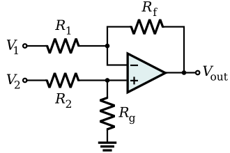
How a Differential Amplifier Circuit Works in Practice
When I design a differential amplifier circuit, I usually start from the simplest op-amp configuration and build upward based on performance requirements.
The basic operation follows this principle:
Two input signals are applied: V1 and V2
The circuit calculates the difference: (V1 - V2)
That difference is then multiplied by a gain factor
This makes the output proportional only to the signal difference, not the shared voltage.
In practical PCB implementations, resistor matching is extremely important. Even small mismatches can reduce common-mode rejection and introduce measurement errors. That's why layout symmetry and component selection matter as much as the schematic itself.
For engineers working on high-precision boards, manufacturing quality becomes part of circuit performance—tight fabrication tolerances, consistent layer alignment, and stable copper geometry all directly influence analog performance. PCBgogo's advanced PCB manufacturing capabilities are built to meet exactly these requirements.
Differential Amplifier Gain: How It Is Determined
Understanding differential amplifier gain is essential for controlling how much a signal is amplified without introducing distortion or noise.
In a typical op-amp-based configuration, gain is set by resistor ratios. The general idea is:
Gain depends on the ratio of feedback resistors
The circuit amplifies only the differential input
Common-mode signals are ideally rejected
What I pay attention to in real designs is not just the theoretical gain, but how it behaves after PCB implementation. Parasitic resistance, trace inductance, and resistor tolerances can slightly shift the expected gain.
A practical takeaway: even if two circuits are designed with identical gain equations, their real-world performance may differ based on layout symmetry and component consistency.
This is why prototype validation is essential before final production. A well-fabricated board ensures that calculated differential amplifier gain aligns closely with measured results.
PCB Design Considerations for Differential Amplifier Circuits
When working on analog front-end designs, PCB layout becomes just as important as circuit theory.
For a stable differential amplifier circuit, I focus on:
1. Matched trace routing
Keep both input traces equal in length and environment exposure to preserve signal balance. For differential pairs especially, consistent impedance controlacross the trace length is critical—any variation in dielectric thickness or copper width introduces asymmetry that degrades common-mode rejection directly.
2. Grounding strategy
A clean analog ground reduces interference and improves common-mode rejection.
3. Component symmetry
Resistors in differential networks should be placed close together to reduce thermal and electrical variation.
4. Noise isolation
Separate high-speed digital signals from sensitive analog paths.
Even small layout asymmetries can degrade performance, especially in high-gain applications.
At this stage, fabrication quality plays a major role. A manufacturer like PCBgogo can help maintain consistent impedance control, precise drilling, and stable copper thickness, which are all important when the differential amplifier circuit is used in precision systems.
Real-World Applications of Differential Amplifiers
In practical engineering environments, differential amplifiers show up everywhere:
Sensor signal conditioning (temperature, pressure, strain gauges)
Audio input stages
Medical instrumentation (ECG, EEG front ends)
Industrial measurement systems
ADC input protection and conditioning
In all these cases, the key requirement is the same: extract a small signal from a noisy environment without distortion.
What makes the differential amplifier especially valuable is its ability to maintain accuracy even when electrical noise is present on both input lines.
Common Design Challenges
From experience, the most common issues in differential amplifier circuit design include:
Poor resistor matching leading to low common-mode rejection
Layout asymmetry introducing noise imbalance
Incorrect gain selection causing signal clipping
Ground loop interference in mixed-signal systems
These problems are often not visible at schematic level. They only appear during prototype testing, which is why iteration and careful PCB fabrication are essential steps in the design cycle.
FAQ: Differential Amplifier Circuit
1. What is the main purpose of a differential amplifier?
The main purpose is to amplify the voltage difference between two input signals while rejecting any noise that is common to both inputs.
2. What is the differential amplifier used for in electronics?
It is commonly used in sensor interfaces, audio systems, medical devices, and any application where weak signals must be extracted from noisy environments.
3. How is differential amplifier gain controlled?
Differential amplifier gain is typically controlled by resistor ratios in the feedback network of an op-amp-based design.
4. Why is PCB layout important for differential amplifier circuits?
Because mismatched traces, grounding issues, or poor symmetry can reduce noise rejection and affect the accuracy of the output signal.
5. Can manufacturing quality affect amplifier performance?
Yes. PCB fabrication precision influences resistance balance, signal integrity, and overall circuit stability, especially in high-precision analog designs.





